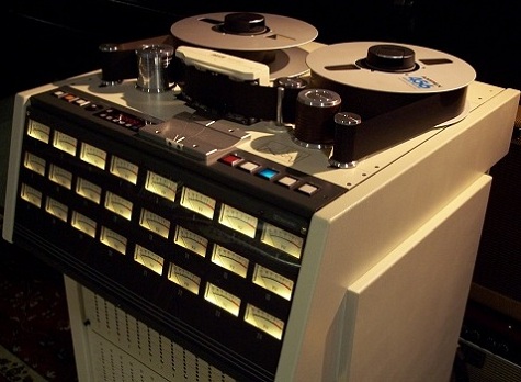
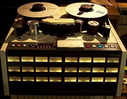
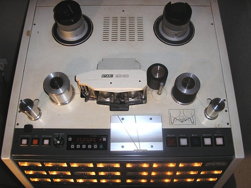
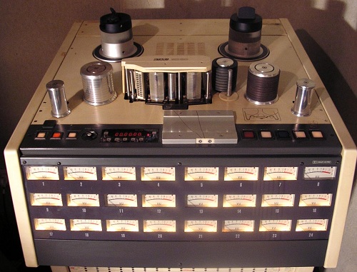
Otari MX-80 Series Tape Recorders
The Otari MX-80 series machines are extremely versatile, high performance 8, 16, or 24 track recorder/reproducers using 1" or 2" wide tape and 10-1/2” NAB reels. The MX-80 series consists of eight machines, each having a different combination of tape speed pairs (7.5 and 15 ips or 15 and 30 ips) and track configurations (8 tracks, 16 tracks, or 24 tracks).
The MX-80 series tape transport is fully microprocessor controlled to provide precision tape handling characteristics while maintaining the high degree of reliability long associated with the Otari line of professional tape recorders.
The transport controls (PLAY, F.FWD, REWIND, STOP, CUE, EDIT/UNLOAD, etc.) direct commands to the microprocessor which, in turn, controls the activities of the capstan and reel servo circuits to provide the desired operating mode or function. The microprocessor provides two-level illumination for the transport control buttons, dim when “off”, flashing when “ready” to perform a function, and bright when “active” after a function has been selected, giving confirmation of the operating mode to the operator.
The plug-in multi-track head assembly allows replacement of a head assembly without having to perform time-consuming height, wrap, and zenith adjustments. Only the azimuth adjustment need be verified whenever changing heads, or optimizing the alignment for a tape recorded on another tape recorder. The head assembly is equipped with a scrape flutter roller located between the record and reproduce head stacks. A head shield, which is manually moved up and down, is provided in front of the head stacks. The head shield rises automatically in PLAY and RECORD modes.
The capstan shaft is driven directly by a DC servo motor which is controlled by a quartz crystal-based phase-locked-loop servo system. A switch on the transport selects between the two operating speeds (7.5, 15 ips or 15, 30 ips). The speed mode switch on the Remote Control Unit (CB-140 or CB-151) selects between the three available speed modes; FIX — crystal controlled speed selected by the speed switch on the transport, VARI — variable speed +50%, and EXT — variable speed controlled by an external speed reference signal (9,600 Hz nominal).
Constant tape tension is provided by the reel motor servo circuit. The tape tension arms utilize non-contact photo-optical sensors to generate feedback signals for the Reel Control Printed Circuit Board (PCB). Constant tension is applied to the tape in all but Edit/Unload mode to insure fast, accurate, stress free tape handling. Motion sensing and accurate tape speed information are provided by the tachometer roller to the transport control circuits in the form of tach pulses. These tach pulses are also used to control the fast forward and rewind speeds, and to provide tape length information to the direct reading Tape Timer.
Located in the pedestal portion of the MX-80, the audio section contains the Audio Control PCB, the Serial Remote Control PCB, the Audio Amplifier PCBs (8, 16, or 24), and the power supplies for; the various sections of the tape recorder. The Audio Control PCB contains the test signal jack (for application of a test signal to all channels simultaneously), a selector switch for high or low reference flux density and indicators showing the level selected, the bias switch which allows bias setting for two different tape formulations, EQ switch for selecting IEC or NAB equalizer, high/low select switch for output and input level, gapless function on/off switch, Dolby HX Pro* on/off switch and VU meter sensitivity selector switch. The Serial Remote Control PCB contains two on/off switches for the selection of Stop Standby and Fast Standby modes.
The Audio Amplifier PCBs each contain the record, reproduce, sel·rep, and bias electronics for one audio channel. Front panel adjustments are provided for record and reproduce equalization at both currently selected speeds, record, reproduce and sel·rep gain, record phase compensation and reproduce low frequency compensation for each speed of the current speed pair, and individual channel bias adjustment. Each channel is provided with an individual
LINE OUTPUT Jack on the front panel, for test purposes, in addition to the XL type OUTPUT connector provided on the rear of the machine. A VU meter is provided for each channel. In each VU meter are two LED indicators, one to indicate signal level peaks that are too short to cause the VU meter to indicate accurately, and another to indicate the channel’s Record status.
Each MX-80 series tape recorder includes either the CB-140 (16 or 24 tracks) or the CB-151 (8 tracks) full function Remote Control Unit. The Remote Control Unit provides control of monitor (Input/Sel·Rep/Repro) and Record Ready switching and indication; transport mode, Search-to-Cue, The CB-140 Remote Control Unit also features four Channel Status memories to store and recall the mode status (Ready/Safe, Mute/Input/Sel·Rep/Repro) of all the channels simultaneously.
Foundational text courtesy of Otari, Inc.


Otari MX-80 Series Tape Recorders
Do you have content, to add, about the Otari MX-80 Series Tape Recorders or associated topics? Please feel free to Share it, here!
What other Visitors have said about the Otari MX-80 Series Tape Recorders.
Click below to see contributions from other visitors to this page...
32 Tracks Not rated yet
Otari made a 32 track version of the MX-80. It used 2" tape on the standard transport.
I installed one during the installation of Pacific Gold Studios …
Return from Otari MX-80 Series Tape Recorders to Magnetic Tape Recorders and Reproducers Return from Otari MX-80 Series Tape Recorders to History of Recording - Homepage |