Teletronix LA-2A Leveling Amplifier
Message Board -Teletronix LA-2A Limiting Amplifier
INTRODUCTION
The Teletronix Leveling Amplifier will automatically reduce audio peaks which might otherwise over drive broadcast or recording equipment.
Automatic gain reduction is accomplished by the use of an electro-optical variable attenuator, which is placed ahead of the first amplifier stage. The attenuation is controlled by the amplitude of the LA-2A input signal.
This system permits up to 40 DB of instantaneous gain reduction, yet causes no wave form or harmonic distortion. The amplifier provides sufficient gain and output level (10 DBM nominal) to be used as a line or program amplifier, or for direct connection to the transmitter in the case of radio and TV operation. Provisions are made for interconnection of the optical attenuators to provide equal gain reduction in both channels when two of the LA-2A Leveling Amplifiers are used for FM stereo broadcasting.
CIRCUIT DESCRIPTION
The LA-2A Leveling Amplifier will produce essentially instantaneous gain reduction of over 40 DB with no increase in harmonic distortion.
Compressor action occurs from the breakaway point at -30 DB input and up to -20 DB, at which point the curve becomes horizontal to exhibit limiting action. The input increases an additional 20 DB, but the output increases less than 1 DB. The leveling amplifier thus combines the the characteristics of a compressor and a limiter. A reasonable amount of care in gain riding will restrict normal operation to the compression region, but uncontrolled output levels will be prevented by the limited action.
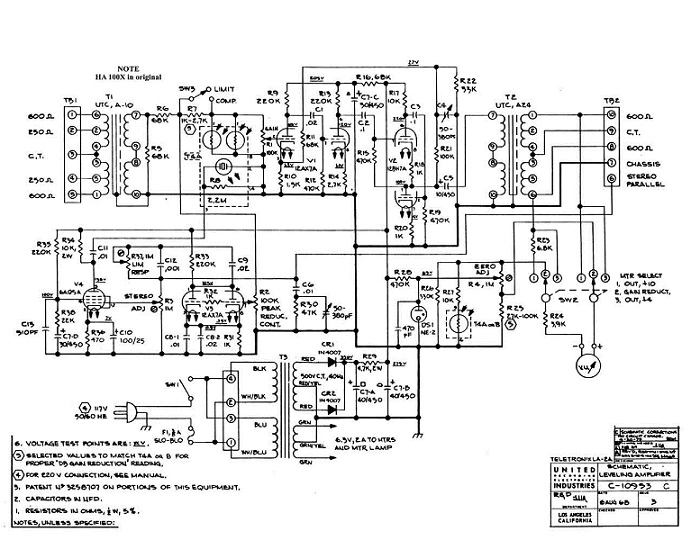
The heart of the leveling amplifier is the electro-optical attenuator which is placed ahead of the first amplifier stage. The actual stage gains and and tube operating parameters are not varied, permitting the tubes to operate at optimum conditions regardless of the amount of gain reduction. The optical attenuator consists of a photo-conductive cell, which is optically coupled to an electroluminescent light source. The electro-luminescent device provides a light intensity which is proportional to the audio voltage applied to its terminals.
Not unlike a capacitor in construction, the electro-luminescent lamp consists of a plate of glass or plastic coated with a clear conducting material on one side and a thin layer of phosphor on the other side. A metallic plate contacts the phosphor coating. As alternating current is applied to the conducting plates the phosphors are excited by the voltage across the dielectric and light is produced. The amount of light depends upon the applied voltage and frequency. The gain or level controlling element is the photo-conductive cell. The resistance of the cell decreases with an increase in the impinging light. Since the light is produced directly from the audio voltage, the response is instantaneous. Rectification and filtering of the audio to produce a control signal are not necessary as in the case of conventional limiters. This system results in automatic level control whose speed of operation is limited only by the response of the variable resistance photo cell used.
A cell is selected which provides a minimum attack time, and a release time which requires about 60 milliseconds for 50% release, and then a gradual release over a period of 1 to 15 seconds to the point of complete release.
The input signal is applied directly to the optical attenuator from the high impedance winding of the input transformer. The amount of introduced by the optical attenuator is controlled by the audio voltage applied to the 6AQ5 which is the luminescent driver amplifier. The amount of signal applied to the 12AX7A voltage amplifier is also controlled by the manual gain control. The voltage amplifier stage provides a gain of 40 DB. Overall amplifier feedback of approximately 20 DB provides low distortion, flat response, and gain stability.
The output stage is somewhat unconventional in that a totem pole or double cathode follower is used. This output stage can tolerate great amounts of output impedance mismatch, but retains low distortion and flat frequency response.
For stereo broadcasting applications, a portion of the input signal is fed through the gain reduction control to the 12AX7A control amplifier. The output at this stage is applied to the stereo balance control and is brought out out to a terminal on the chassis. For stereo operation, this terminal is connected to the same terminal on an identical amplifier and control voltage becomes common to both units. A gain-reduction control voltage in either amplifier will cause equal gain reduction in both units. The control voltage is applied to the stereo balance control to the 6AQ5 driver amplifier. This stage provides the necessary voltage to operate the electro-luminescent light source.
Foundational text courtesy of Teletronix Operating Manual and associated literature.

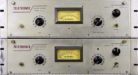
Pair of Teletronix LA-2A Leveling Amplifiers.

Skip Juried, in Session, with four Teletronix LA-2A Leveling Amplifiers at Sound Exchange Studios, NY. Photo Courtesy of Chris Juried

Teletronix LA-2A Leveling Amplifier
Do you have content, to add, about the Teletronix LA-2A Leveling Amplifier or associated topics? Please feel free to Share it, here!
Return from Teletronix LA-2A Leveling Amplifier to Outboard Recording Equipment
Return from Teletronix LA-2A Leveling Amplifier to History of Recording - Homepage |


